.
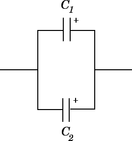
. are components of
 .
.

 and inductive reactance
 contribute to the total reactance
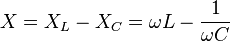
 is the angular frequency,
 times the frequency in Hz
 ,
the reactance is said to be
,
the reactance is said to be
 ,
then the impedance is purely
,
then the impedance is purely
 ,
the reactance is said to be
,
the reactance is said to be
 (or
(or
 .
.
Capacitive Reactance against Frequency

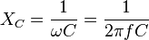
By re-arranging the reactance formula above, we can also find at what frequency a capacitor will have a particular capacitive reactance ( XC ) value.
Example No2 – At which frequency would a 2.2uF Capacitor have a reactance value of 200Ωs?

Or we can find the value of the capacitor in Farads by knowing the applied frequency and its reactance value at that frequency.
Example No3 – What will be the value of a Capacitor in farads when it has a capacitive reactance of 200Ω and is connected to a 50Hz supply.

We can see from the above examples that a capacitor when connected to a variable frequency supply, acts a bit like a “frequency controlled variable resistor”.
At very low frequencies, such as 1Hz our 220nF capacitor has a high capacitive reactance value of approx 723KΩs (giving the effect of an open circuit).
At very high frequencies such as 1Mhz the capacitor has a low capacitive reactance value of just 0.7 ohms (giving the effect of a short circuit).
At zero frequency or steady state DC the capacitor has infinite reactance looking more like an “open-circuit” between the plates and blocking any flow of current through it.